Benchtop instrument enclosure
A bent aluminum shell with separate panels and a removable electronics tray. The same source builds a compact 220 mm body and a 260 mm version for wider electronics.
Completed CAD and theoretical manufacturing study. No fabricated enclosure, ingress rating, EMC test, electrical safety qualification or production process capability is claimed.
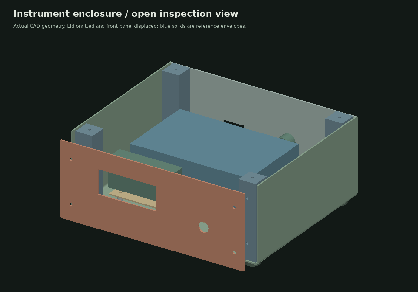
Assembly decisions
The U-shell provides the base and two side walls. Machined corner posts keep panel attachment independent of bent sheet tabs, at the cost of added mass and machining. Four square corner posts carry the front, rear and top fasteners. The posts sit 2.5 mm inside the vertical sheet faces so their lower corners clear the formed bends. The originally evaluated 0.5 mm setback is rejected in the additional study because it intersects the bend material.
The tray uses four 10 mm spacers. Separate M3 x 6 screw envelopes enter the spacer from the base and tray sides, leaving a 1 mm axial gap between screw tips. This allows the tray to lift out after removing its four top screws, with the base screws and spacers remaining in place. The wiring harness must be disconnected first. The 6 mm foot envelopes clear the underside screw heads.
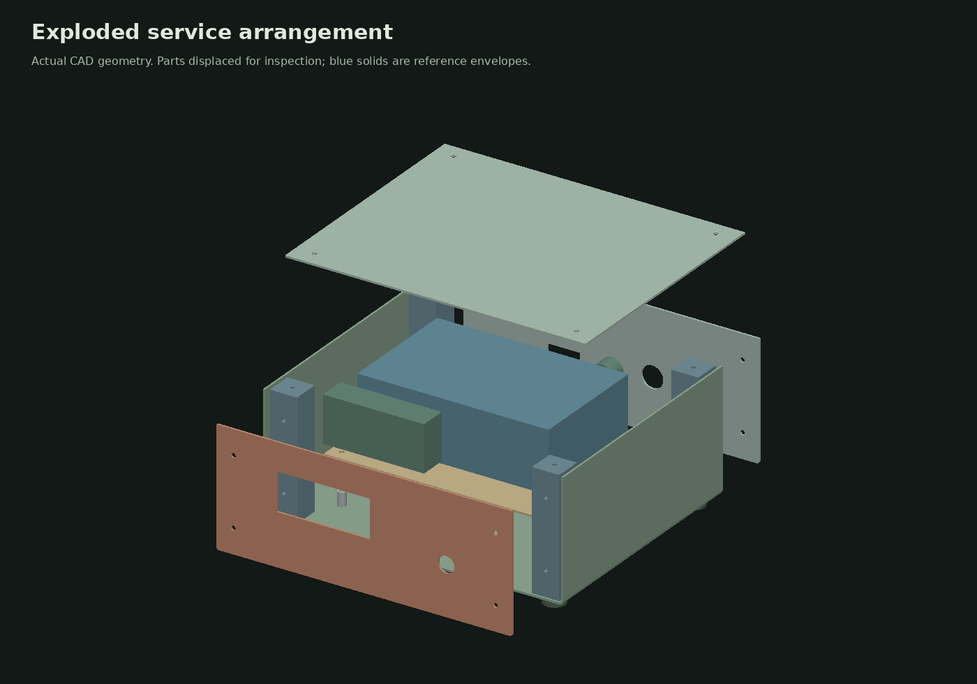
Dimensions and fit
| Configuration | Body W x D x H (mm) | Tray W x D (mm) | Assembly mass estimate (kg) | Solid-solid collisions |
|---|---|---|---|---|
| compact | 220 x 180 x 90 | 170 x 120 | 1.076 | 0 |
| wide | 260 x 180 x 90 | 210 x 120 | 1.181 | 0 |
Body dimensions exclude the feet and exposed screw heads. CAD and mass estimates include 49 modeled solids per configuration. Density inputs are 2680 kg/m3 for aluminum, 7850 kg/m3 for steel and 1100 kg/m3 for elastomer. Fastener volumes are nominal unthreaded envelopes. Electronics are not included in the mass estimate.
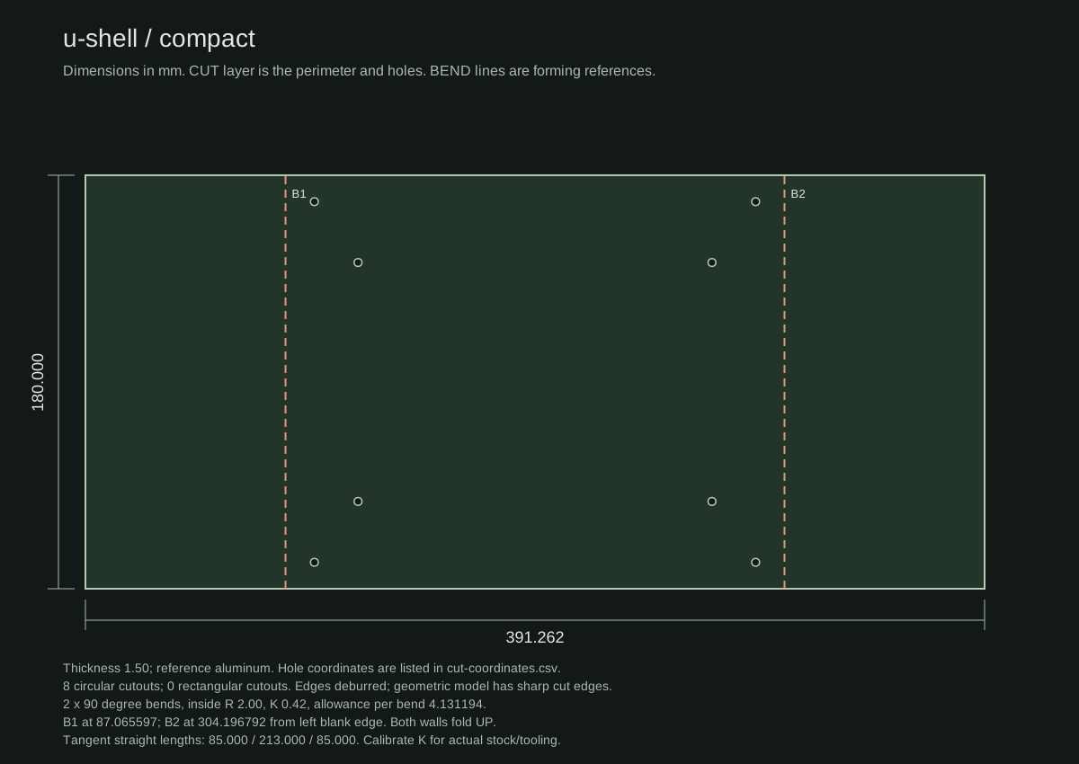
Flat development
The two bends are modeled as concentric quarter-annular sections with a 2.0 mm inside radius and 1.5 mm thickness. The DXF is derived along a declared neutral axis, rather than projected from the folded body.
BA = (pi / 2) * (R + K*t)
Lflat = B + 2*V + 2*BA
B = W - 2*(R + t)
V = H - t - (R + t)
dLflat/dK = pi*t
For the compact body: B = 213.000 mm, V = 85.000 mm and BA = 4.131194 mm per bend at K = 0.42. The developed width is 391.262389 mm. The BEND layer contains bend-center reference lines. CUT contains closed outlines and holes; curved panel corners use exact DXF arc bulges.
K = 0.42 is an input assumption, not a material certification. A real bend coupon and actual tooling must establish compensation before manufacturing. The completed theoretical run evaluates both a narrow calibrated K interval and a rejected wider interval. The constant-thickness CAD bend uses the geometric mid-surface for volume, whereas the developed blank uses the declared K. Those idealizations produce a small, explicitly reported shell mass difference; flat-stock area is not forced to match the constant-thickness bent volume.
| Configuration | Bend allowance (mm) | Blank width (mm) | CAD shell volume (mm3) | Developed-blank volume (mm3) | Difference (%) |
|---|---|---|---|---|---|
| compact | 4.131194 | 391.262389 | 105633.682 | 105531.895 | 0.096 |
| wide | 4.131194 | 431.262389 | 116433.682 | 116331.895 | 0.087 |
Service and cable clearances
| Compact check | Worst-case margin (mm) | Interpretation |
|---|---|---|
| Panel fit | 0.156 | Total across both sides after forming and panel-width tolerances |
| Tray/post clearance | 0.750 | Per side; tray lifts straight up |
| Cable bend envelope | 2.700 | Behind electronics; R25 cable centerline plus 3 mm cable radius |
| Screw clearance | 0.070 | Clearance-hole radius less two independent position budgets |
The display cutout is 68 x 28 mm. The round front opening is 12 mm diameter; the rear has a 16 mm circular opening and a 24 x 12 mm rectangular opening. These are declared reference interfaces, not a commercial connector drawing. The rear cable check reserves 12 mm of connector depth and a 25 mm cable bend radius. A 35 mm bend-radius requirement is deliberately rejected in the additional study.
Collision checks include all manufactured solids and nominal hardware; only mathematical surface contact is tolerated. A separate vertical tray-removal sweep checks seven displacements from 0 to 100 mm against the fixed enclosure. A 10 mm-diameter tool cylinder checks access to each tray screw. The sweep is a sampled geometric check plus an analytical side-gap bound, not a flexible harness simulation.
Files and reproduction
python -m pip install -r requirements.txt
python run.py
python test_project.py
python complete_validation.py
The CLI also accepts python run.py --inputs inputs.json --output outputs. Both configurations are rebuilt from the input file. The reference reports and acceptance records always use the included inputs; alternate runs write their own summary in the selected output folder.
- Compact assembly STEP and wide assembly STEP
- Compact assembly STL
- Developed shell DXF and cut coordinates
- Orthographic assembly drawing
- Corner-post drill/thread schedule
- Compact bill of materials
- Verification record and additional manufacturing and service study
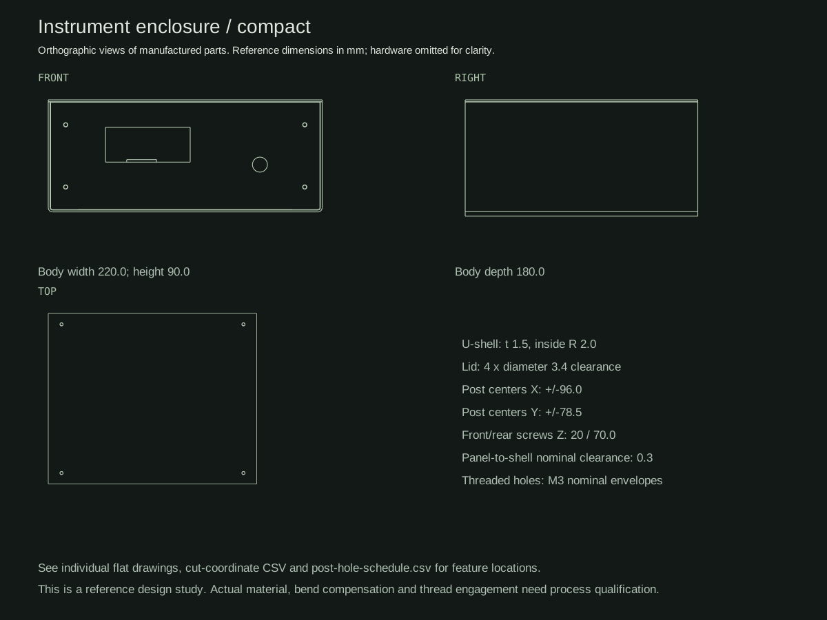
Verification and limits
Each export is checked for valid solid geometry, pairwise interference, analytic shell-volume agreement, hole location, STEP round-trip volume and DXF reconstruction. Flat panels reconstructed from CUT-layer DXF agree with their 3D counterparts. The shell comparison accounts for the neutral-axis model difference separately.
Threads, surface finish, sheet temper, bend springback, cut-edge quality, production tooling, adhesive foot retention and loaded vibration are not physically measured. Nominal screw envelopes do not demonstrate thread strength. No enclosure pressure, impact, electrical, thermal, EMC or ingress rating is inferred. The deliverable is a completed reference geometry and fit study for low-voltage instrumentation, not a certified product.
References
- SOLIDWORKS: K-factor and bend allowance equation. Used to define neutral-axis arc length; K remains a declared project input.
- SOLIDWORKS: bend allowance and flat-length definitions.
- CadQuery: STEP, STL and DXF import/export.