Sheet-metal and assembly design
Benchtop instrument enclosure
A bent instrument enclosure with removable panels and an electronics tray. Two body widths share parametric CAD, developed flat patterns, drawings and tolerance checks.
Parametric CAD with completed fit and manufacturing study
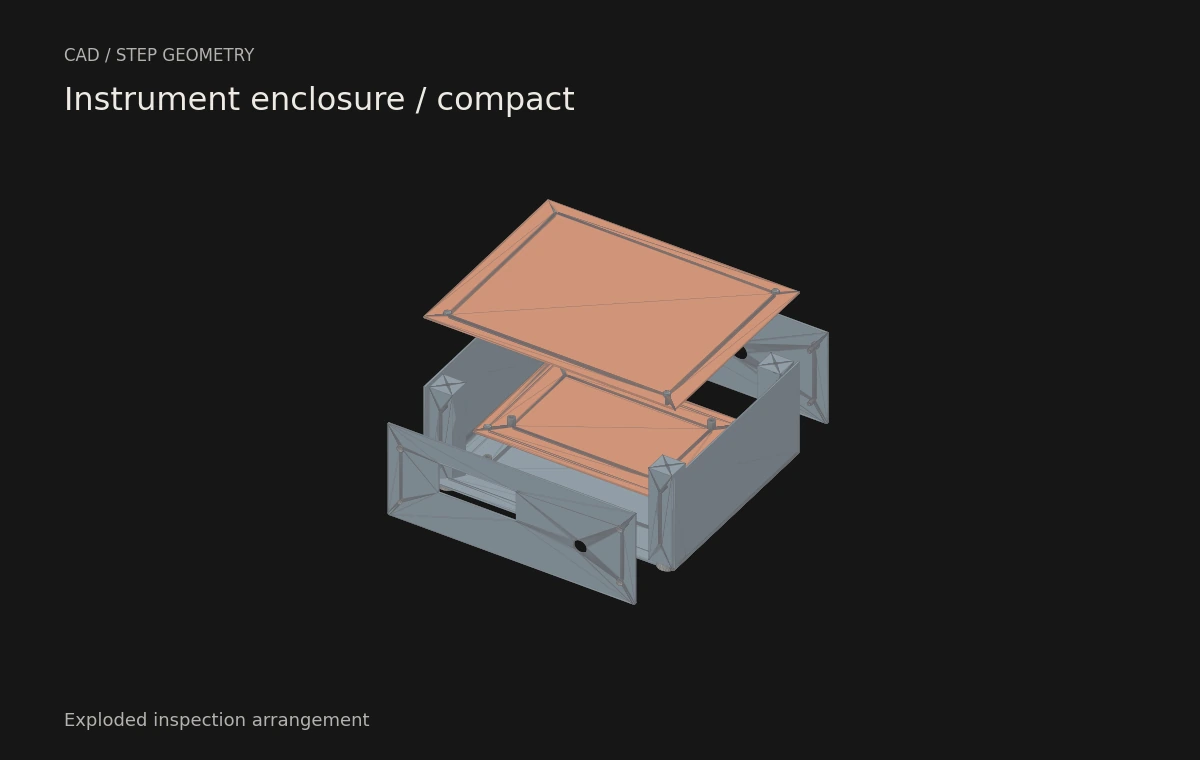
Implementation
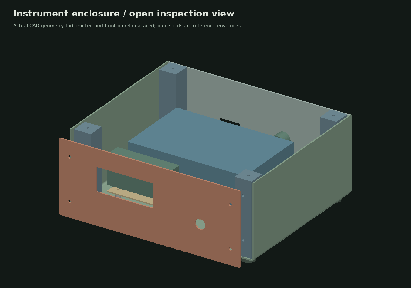
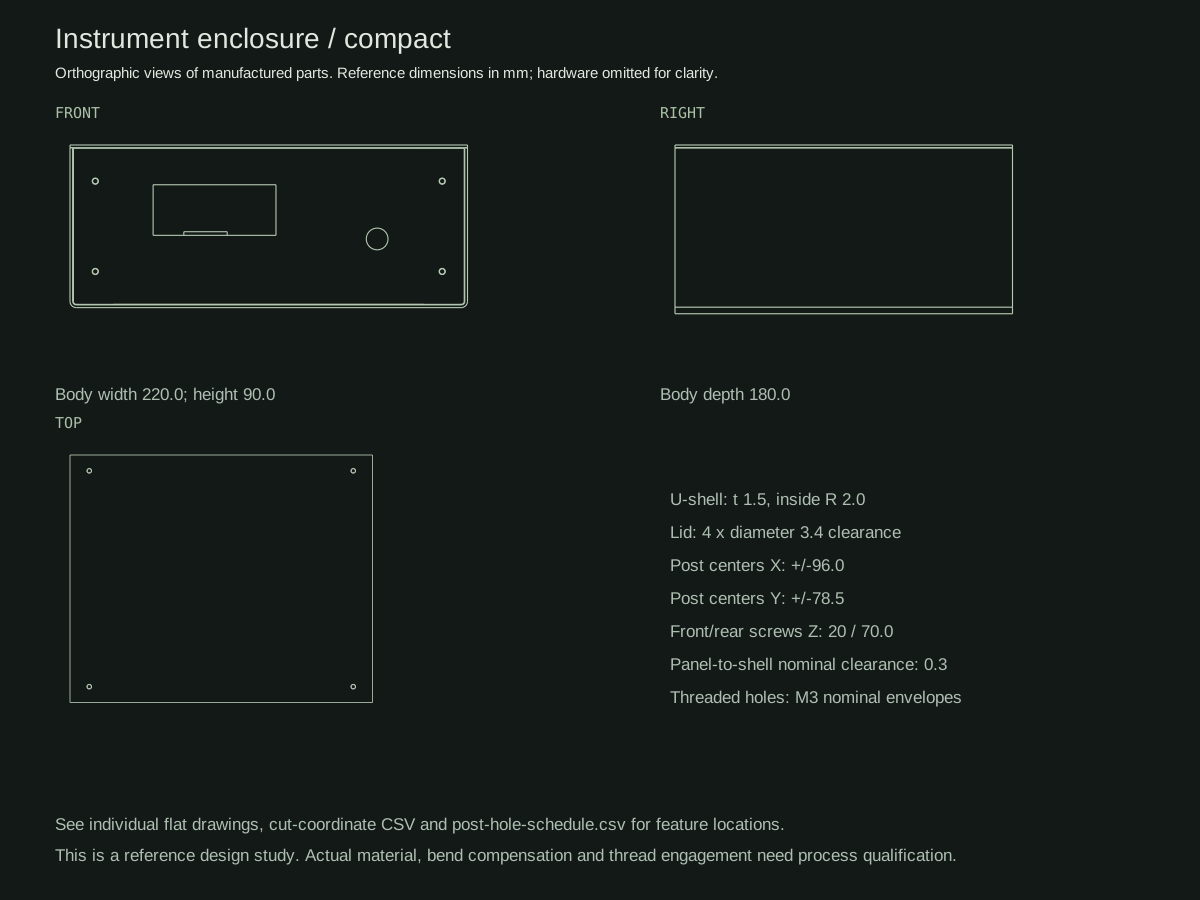
A constant-thickness U-shell with true concentric quarter-annular bends, separate front/rear panels and a removable lid.
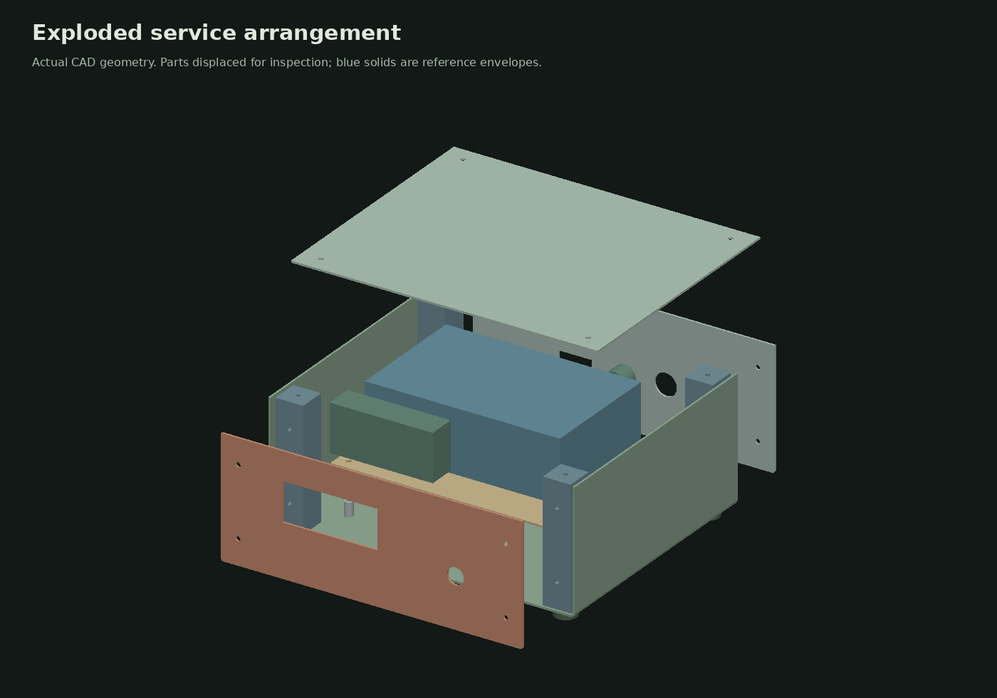
Two 49-solid assemblies generated from the same dimensional inputs; nominal fasteners and threads are simplified envelopes.
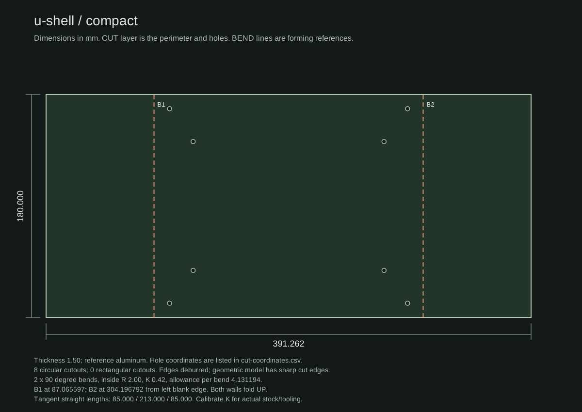
Developed DXF patterns use neutral-axis bend allowance, exact panel-corner arcs and separate CUT/BEND layers.
The selected post setback removes the bend interference found in the rejected arrangement. Separate screws at each end of the tray spacers permit top-side tray removal.
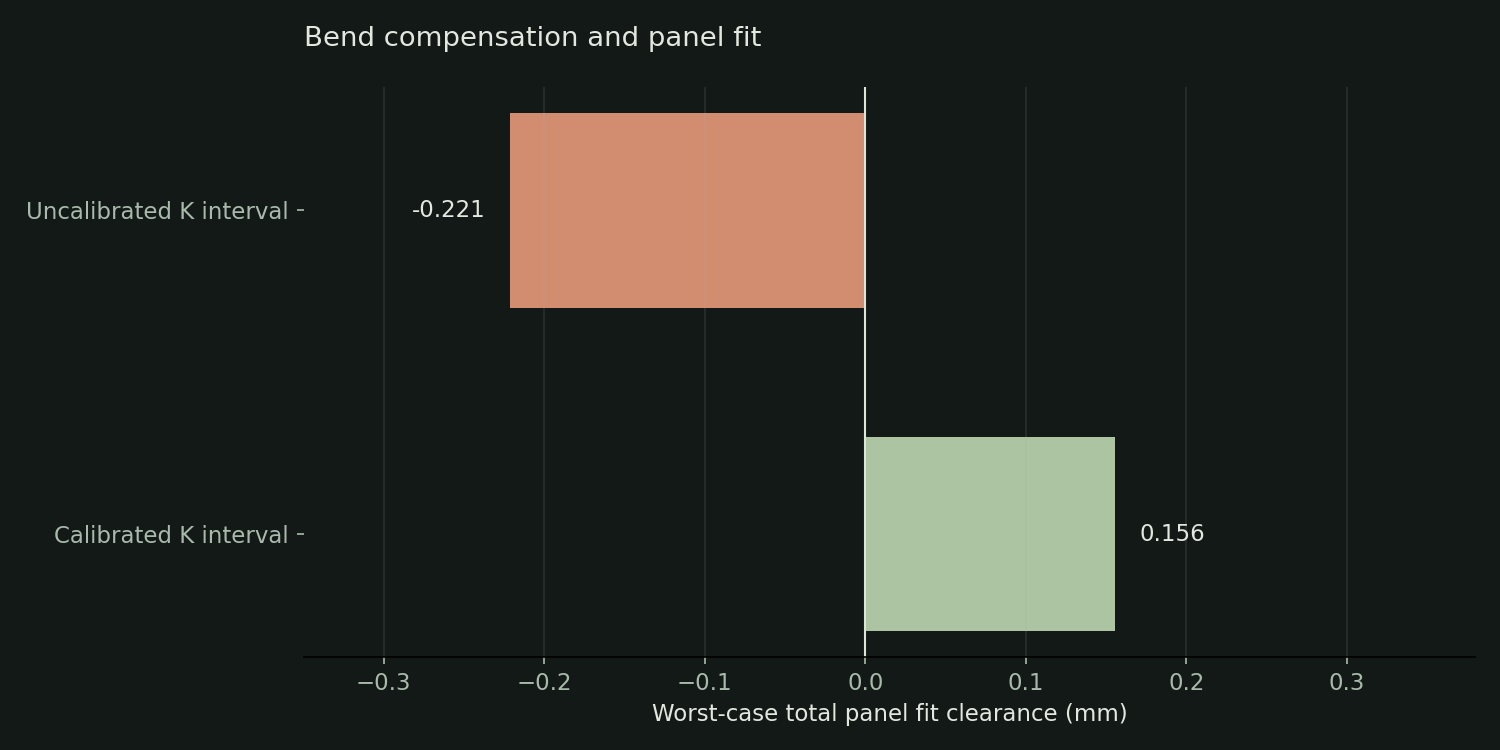
Executed manufacturing/service study includes 32 tolerance corners, 500 synthetic inspection rows and deliberately rejected cable/tool/compensation alternatives.
Inputs and assumptions
- Reference 140 x 90 x 45 mm electronics volume and declared display/connector apertures; no commercial component footprint is implied.
- 1.5 mm reference aluminum sheet, 2 mm inside radius and nominal K factor 0.42. Actual stock, temper and tooling are not qualified.
- The stated manufacturing tolerances and cable bend radius are explicit design inputs, not measured shop capability.
Results
| Configurations | 2 |
|---|---|
| Solids per assembly | 49 |
| Compact shell developed width | 391.262389 mm |
| Compact assembly mass estimate | 1.0756 kg |
| Worst-case total horizontal panel clearance | 0.155752 mm |
| Worst-case tray side clearance | 0.75 mm |
| Worst-case cable-envelope margin | 2.7 mm |
| Synthetic inspection rows | 500 |
Report figures (4)
Verification
26 geometric/export checks and 16 regression tests pass. An additional 14 manufacturing/service outcomes match expectations, including correctly rejected alternatives. Both 49-solid assemblies have no positive-volume overlaps; STEP round trips and DXF reconstructions agree with their reference geometry.
python run.py && python test_project.py && python complete_validation.pyAdditional scenarios
14 outcomes checked through synthetic/theoretical. The report lists the expected and observed outcomes for each check.
Read the validation report ↗Project files
The ZIP contains the source, inputs, results, and instructions. These files are also available individually.
- Parametric CAD sourcemodel.py · 9 KB
- Dimensions and tolerance inputsinputs.json · 1 KB
- Compact assembled STEPoutputs/compact/cad/assembly.step · 857 KB
- Compact exploded STEPoutputs/compact/cad/exploded.step · 855 KB
- Wide assembled STEPoutputs/wide/cad/assembly.step · 858 KB
- Compact STLoutputs/compact/cad/assembly.stl · 1.3 MB
- Developed U-shell DXFoutputs/compact/flat-patterns/u-shell.dxf · 17 KB
- Front panel DXFoutputs/compact/flat-patterns/front-panel.dxf · 16 KB
- Rear panel DXFoutputs/compact/flat-patterns/rear-panel.dxf · 16 KB
- Lid DXFoutputs/compact/flat-patterns/lid.dxf · 16 KB
- Electronics tray DXFoutputs/compact/flat-patterns/electronics-tray.dxf · 16 KB
- Orthographic assembly drawingoutputs/compact/drawings/assembly.svg · 73 KB
- Dimensioned shell flat drawingoutputs/compact/drawings/u-shell.svg · 3 KB
- Compact bill of materialsoutputs/compact/bom.csv · 4 KB
- Flat-pattern coordinate scheduleoutputs/compact/cut-coordinates.csv · 1 KB
- Corner-post hole/thread scheduleoutputs/post-hole-schedule.csv · 1 KB
- Geometry/export resultsoutputs/summary.json · 12 KB
- Synthetic manufacturing observationscompletion/synthetic-inspection.csv · 63 KB
- Manufacturing and service studycompletion/report.html · 6 KB
- Acceptance record and source hashescompletion.json · 6 KB
- Main reportreport.html · 10 KB
Archive checksum
SHA-256
bd0f598730f816d45f06221121ca8c85690bc59c66094379590f8328303b27b4Run locally
Python 3.12 / CadQuery 2.7.0 / NumPy 2.3.5 / Matplotlib 3.10.8 / ezdxf 1.4.4 / Pillow
Extract the ZIP and open a terminal in the instrument-enclosure folder. The README includes setup and usage details.
python -m pip install -r requirements.txt
python run.py
python test_project.py
python complete_validation.py
Limits
- The work is a completed geometry, export, fit and theoretical manufacturing study; no fabricated enclosure or measured production capability is claimed.
- The K-based developed blank and constant-thickness bend CAD use distinct idealizations. Their small shell-volume difference is quantified in the report.
- Thread geometry, material temper, cut-edge finish, springback, adhesive-foot retention and actual component drawings require physical process qualification.
- No strength, shock, electrical, thermal, EMC or ingress rating is inferred. Rigid component/cable envelopes do not simulate a flexible connected harness.